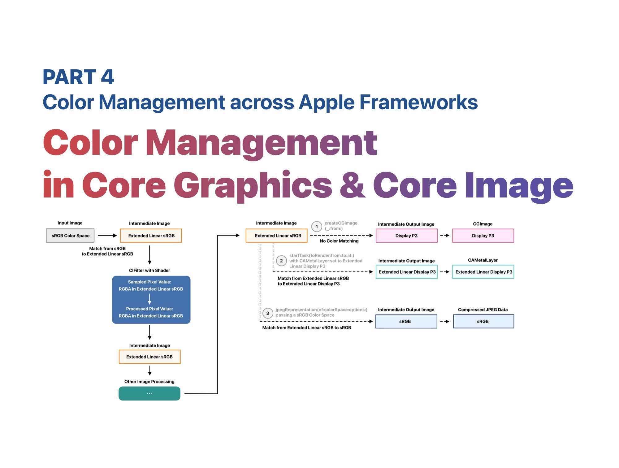
Color Management across Apple Frameworks. Part 4: Color Management in Core Graphics & Core Image

This article is the fourth part of this series. It’s recommended to read the previous three parts of this series first.


Before we dive into specific APIs in Core Graphics and Core Image, let’s recap what color management is:
Color Management is the process that ensures colors appear consistent across different devices and environments. Apple provides built-in automatic color management in frameworks like Core Graphics and Core Image, which helps developers avoid the complexity of handling it manually.
Color Matching is a subset of color management. It refers to converting a color from one space to another—say, from sRGB to Display P3—so that it looks visually the same, or as close as possible, across different devices.
Typically, you should avoid handling color management manually, as incorrect implementation can easily introduce bugs and lead to inconsistent visual results.
Core Graphics
We have mentioned some basic color space information regarding the CGImage and the CGContext previously. When creating a CGContext , you will be asked to pass a ColorSpace:

The CGColorSpace passed here means:
It’s the working color space of the
CGContext. If you draw sampled images that have different color spaces, color matching using the specifiedRenderingIntentwill be applied to make sure colors appear to be similar in different gamuts.
It’s also the output color space when creating an output
CGImageusing themakeImage()method.
The default Rendering Intent of a
CGContextis “default”: Core Graphics uses perceptual rendering intent when drawing sampled images and relative colorimetric Rendering Intent for all the other drawings. You can use thesetRenderingIntent(_:)method to specify a Rendering Intent. Rendering Intents are the algorithms to use for mapping colors from the source gamut to the destination gamut. For more information about Rendering Intents, please refer to this documentation.
The image below illustrates how color management works in Core Graphics:
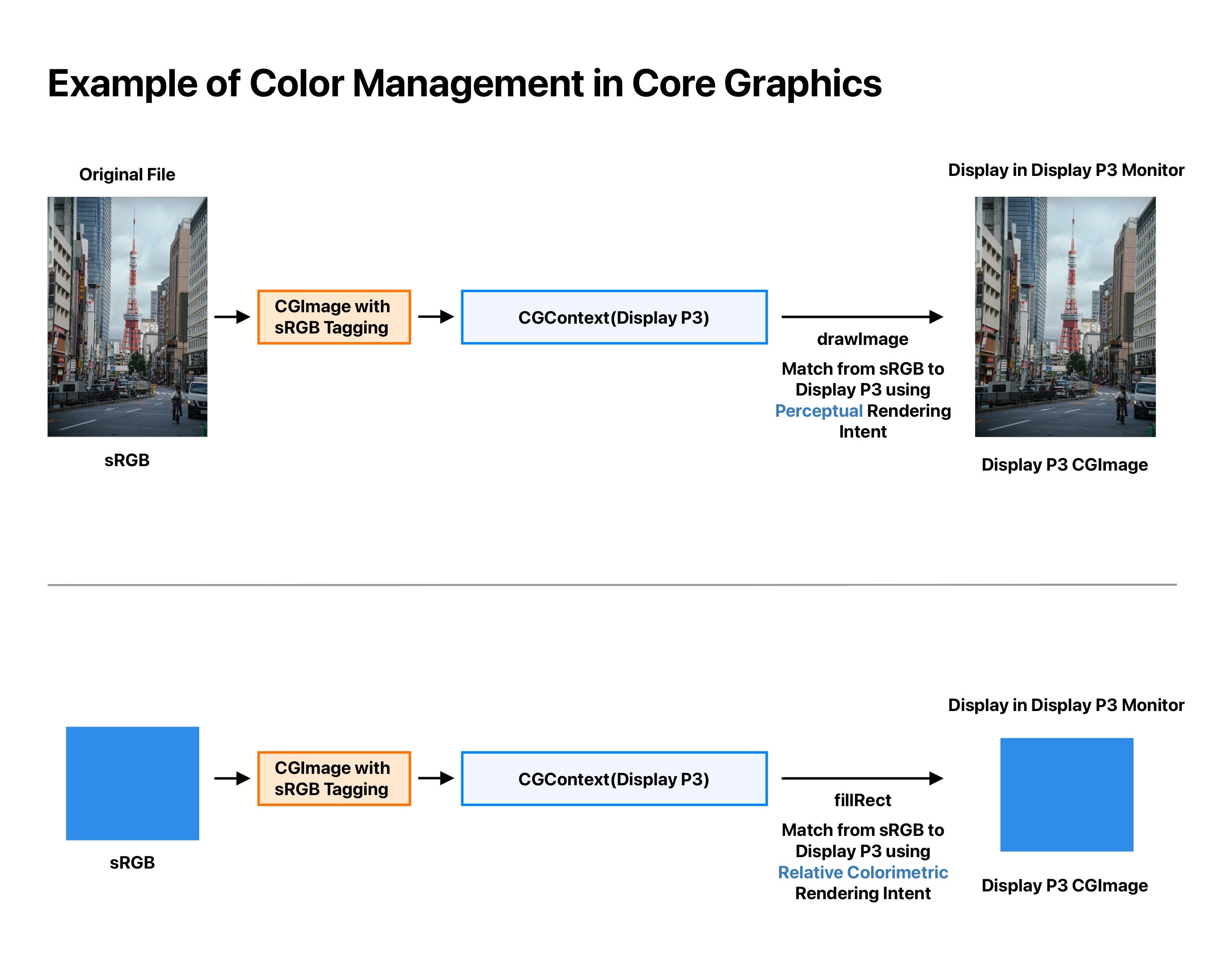
The
CGContextinstances in the example above are working in the Display P3 working color space. Thus, the resultCGImagewill be in the Display P3 color space after calling themakeImage()method.
If the input image or color uses a different color space than the target
CGContext, it will be matched from the source color space to the color space of theCGContextwhen drawing the image or filling the color. In the case above, both the input image and the fill color are in the sRGB color space. They will be matched from sRGB to Display P3 using different rendering intents (assuming the rendering intent of theCGContextis set to default).
Below is an example when you break the Color Management in Core Graphics.
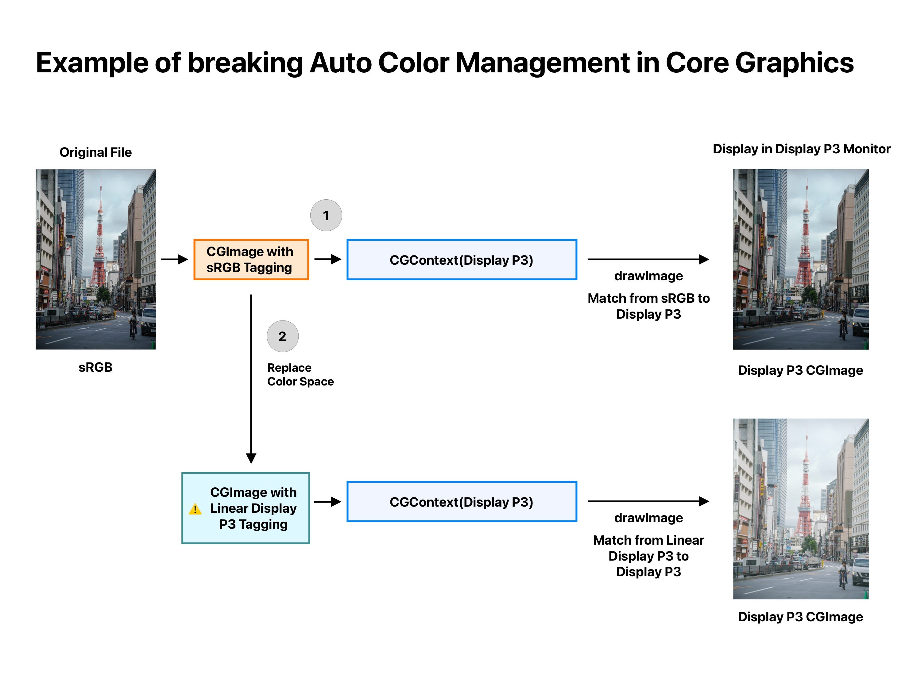
For an sRGB image, when being drawn in a Display P3
CGContextwith perceptual Rendering Intent, the color matching system will do its best to make sure the destination and source images will have a similar look, even they have different color gamuts.
If you use the
copy(colorSpace:_)method to override the color space of an image—for example, assigning a Linear Display P3 color space to an original sRGB image—and then draw it in a Display P3CGContext, the resulting image will appear with brighter shadows and darker tones. This happens because the color matching system will gamma-encode the source linear image, leading to a perceptual shift in luminance.
If you use
CGContextto draw to aCVPixelBuffer, make sure that the bitmap layout matches the pixel format of theCVPixelBuffer, otherwise theCGContextwill fail to create. For example, if you usekCVPixelFormatType_32BGRAas the pixel format to create aCVPixelBuffer, when creating aCGContextusing theinit(data:width:height:bitsPerComponent:bytesPerRow:space:bitmapInfo:)initializer, you need to useCGImageAlphaInfo.premultipliedFirst.rawValue | CGBitmapInfo.byteOrder32Little.rawValueas bitmap info; otherwise, the colors will appear incorrectly.
Core Image
While color management in Core Graphics is relatively straightforward, it becomes much more complex in Core Image and requires extra care when working with its APIs.
We’ve already introduced some of the color space properties of CIContext above. To recap, there are three key color spaces to pay attention to: the input image color space, the working color space, and the output color space. The illustration below shows how these different color spaces interact within a CIContext when rendering an image.
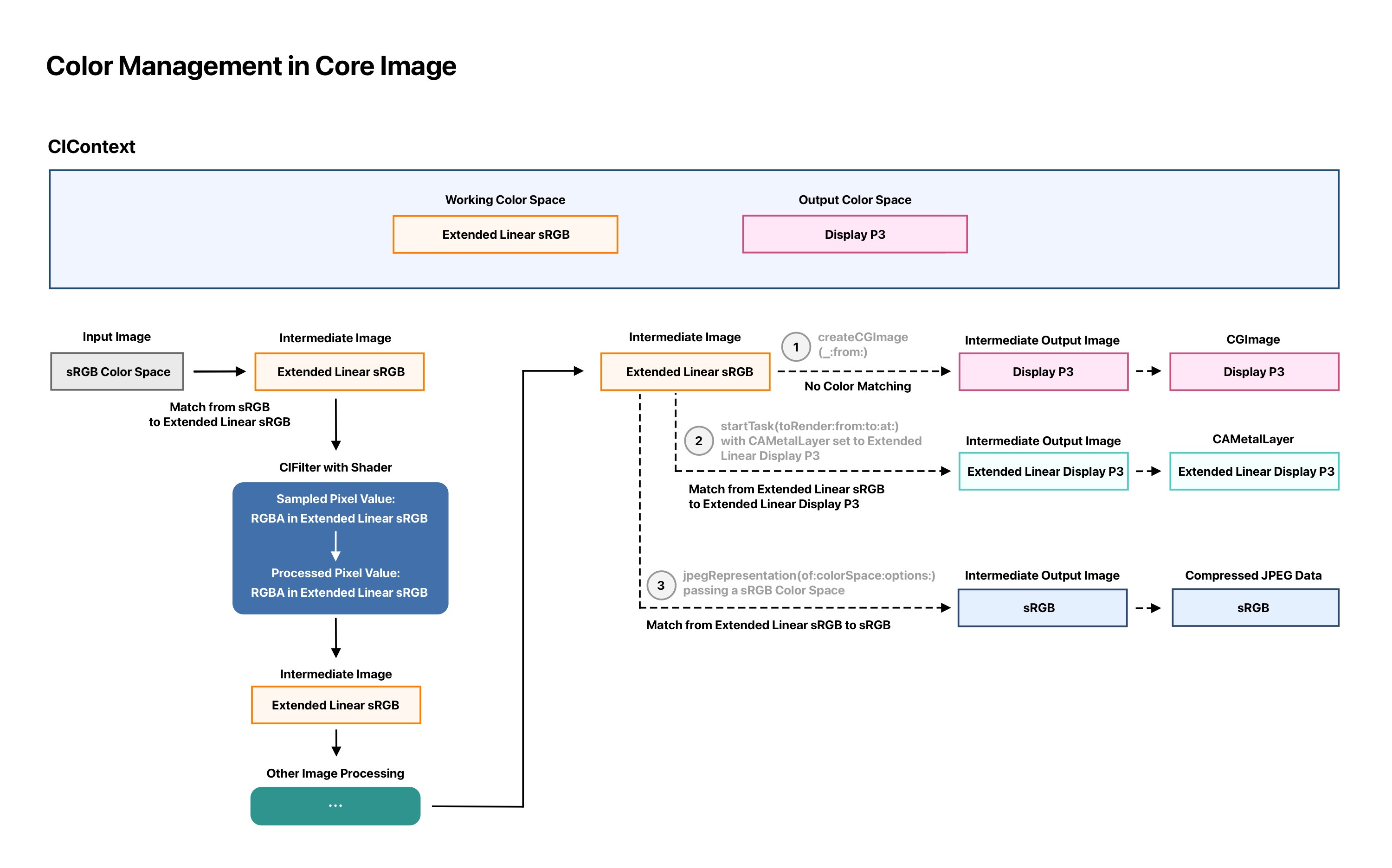
This graph is meant to help you understand the rendering process in Core Image. Internal optimizations may be applied to simplify the graph as much as possible to improve rendering efficiency.
To help you understand the image above, here are a few notes:
The rectangles with border indicate the current color space of each node. For example, for a
CIContextthat has a working color space of Extended Linear sRGB, you can trace how the working color space is used throughout the image processing pipeline by looking for the rectangles with orange borders.
The dashed line represents the output rendering of a
CIContext, which means it renders and draws the content to one of the the destinations. In the image above, there are 3 different destinations: 1. ACGImage2. ACAMetalLayerwithMLTexture3. A compressed JPEG data.
The
CIContextis set to use extended Linear sRGB as working color space and Display P3 as the default output color space.
From the input image on the left to one of the render destinations on the right, here’s how color management works:
The input image is in the sRGB color space. Before it’s processed in a rendering node, it’s first matched from the source color space to the working color space. In this case, an implicit Color Matching from sRGB to Extended Linear sRGB is performed automatically.
For a
CIFilterthat takes an input image, it actually samples from the intermediate image, which is already in the working color space. In other words, when the shader samples pixel values from the sampler, the data is already in extended Linear RGBA form. These pixel values are stored as floating-point numbers and can range from zero to values greater than one (Note: using Extended color space is essential when processing HDR images).
When rendering to the output destinations:
For rendering to a
CGImageusing the createCGImage(_:from:)method (which doesn’t include a colorSpaceparameter), the system uses the output color space previously set—say, Display P3. In this case, Core Image performs color matching from Extended Linear sRGB (the working color space) to Display P3, and then creates a CGImagein that color space.
For rendering to a
CAMetaLayerwith aMTLTexturedefined in the Extended Linear Display P3 usingstartTask(toRender:from:to:at:)method, it will perform color matching from extended Linear sRGB to Extended Linear Display P3.
For rendering to compressed JPEG data using
jpegRepresentation(of:colorSpace:options:)passing a sRGB color space, it will perform color matching from extended Linear sRGB to sRGB, and then create the compressed JPEG data accordingly.
Use debug tool to inspect the render pipeline
As mentioned earlier, the graph above is for demonstration purposes only. Internal optimizations may be applied to simplify the processing nodes as much as possible to improve rendering efficiency.
Fortunately, Apple provides a couple of tools to help developers examine the internal workings of a render pass: the Xcode preview and the CI_PRINT_TREE environment variable.
When you hit a break point in Xcode, you can click the small eye icon of the CIImage instance to open a window to get the visualization of the pipeline graph:
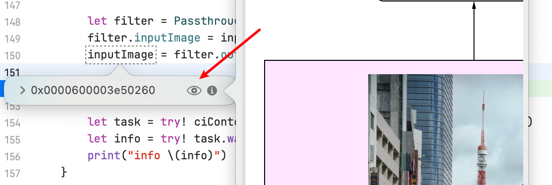
Then, in the opened window, you can inspect how the image is being processed from its original input image to the current screen using an internal CIContext for this preview. Consider the following code:

When inspecting the outputImage instance in Xcode preview, we can get:
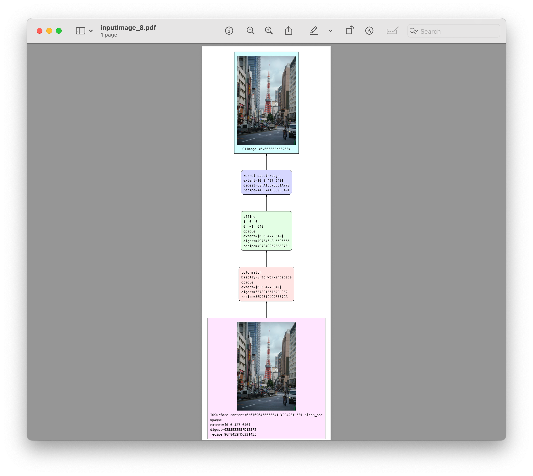
Note that the graph shown above is, again, just the initial process graph before node optimizations. We inspect the rendering process from bottom to top:
At the very bottom, the source image is created, along with some of its metadata—such as its extent and original pixel format.
Next comes a color match from Display P3 (the source image’s color space) to the working color space of the
CIContext.
Then, a vertical flip transformation is applied to the intermediate image.
Finally, the intermediate image is served as the source image to the
passthroughkernel we defined.
Additionally, you can print a CIImage’s debugDescription property to get similar information in text form:
print("\(outputImage.debugDescription)"

-----
output image <CIImage: 0x600003cbdba0 extent [0 0 427 640]>
  {4} kernel passthrough(src) extent=[0 0 427 640] recipe=660D8401
    {3} affine [1 0 0 -1 0 640] opaque extent=[0 0 427 640] recipe=2EBE870D
      {2} colormatch DisplayP3_to_workingspace opaque extent=[0 0 427 640] recipe=9D85579A
        {1} IOSurface content:6367696400000037 YCC420f 601 alpha_one opaque extent=[0 0 427 640] recipe=DC331455
Inspecting a CIImage directly uses an internal, temporary CIContext. To properly debug the CIContext that renders a CIImage to a destination, you should use the following method to get the pipeline graph:

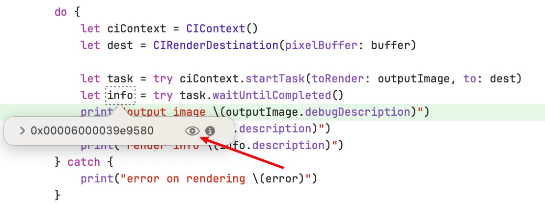
The code above creates a CIRenderDestination with a CVPixelBuffer, and uses the startTask(toRender:to:) method of CIContext to begin a render task. This method returns a CIRenderTask, which can be inspected by hovering your cursor over it.
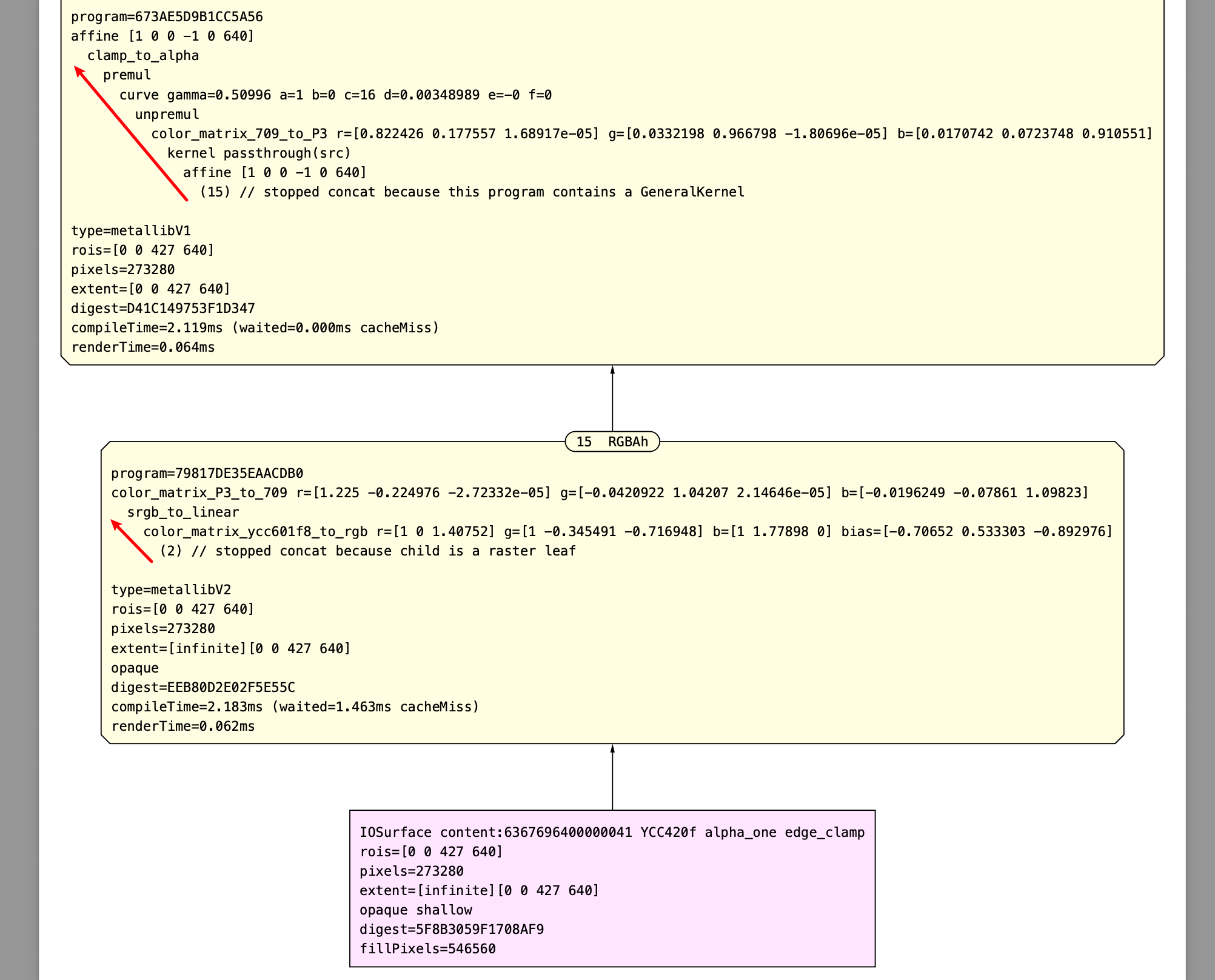
Then you can get the optimized process graph for this render pass. It’s much longer than the initial one, as it represents the actual processing steps involved. Now, let’s first focus on the part where color management does its job before the passthrough kernel:

From bottom to top:
The original image is in YCC420f format, so it’s first converted to RGB using a color matrix.
Then a
srgb_to_linearis applied to gamma-decode the image.
Next, a
color_matrix_P3_to_709is applied to color-match the Display P3 color gamut to the sRGB color gamut (note: sRGB shares the same color gamut as Rec. 709).
Next it flips the image vertically just like before.
Finally the intermediate image is processed by our passthrough kernel.
The CIRenderDestination in this example is initialized from a CVPixelBuffer, which includes attachments that define Display P3 color space in this case. Therefore, after the passthrough kernel, it need to be converted from the working color space (Linear sRGB) to Display P3:

As we can see, after the passthrough kernel, it first use a color matrix to color match from the sRGB (REC. 709) color gamut to Display P3, then it apply a gamma encoding to it.
You can try setting the
colorSpaceproperty of theCIRenderDestinationto see how it affects the color management. For instance, if you change the output color space to Linear sRGB, then no color-matching or gamma-encoding should be applied after thepassthroughkernel. Likewise, you can try setting different working Color Space of theCIContextto see how it behaves.
After we call the waitUntilCompleted() method of the CIRenderTask, we get a CIRenderInfo instance, which can also be used to examine the render result.
The render result includes additional details, such as the compile and render times of the program. Keep in mind that, just like the directional arrow indicates, we should inspect the process graph from bottom to top.
Color Spaces in some built-in CIFilters
Some built-in CIFilters allow us to set the colorSpace of the filter instance, such as CIColorCubeWithColorSpace, CIColorCubesMixedWithMask, and CIColorCurves.
The documentation for these APIs may seem unclear about how color spaces are used internally. Here’s the key takeaway: the colorSpace properties of these APIs define the color spaces that input data will be matched to before any kernel processing occurs. In other words, color matching happens first, aligning the input to the expected working space. As for LUT cubes or curves used to manipulate pixel data, the data itself should be in linear space—meaning no gamma encoding is applied.
How do I draw that conclusion? Let’s find it out using the debug tool we mentioned above. Consider the following code:
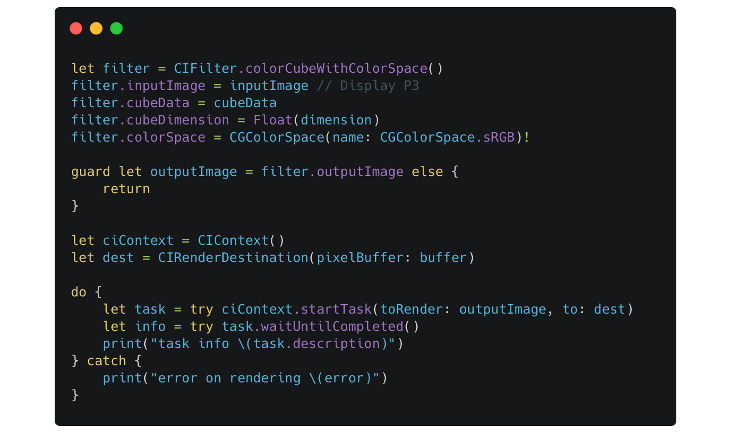
After we print the CIRenderTask, we can get the output like this:
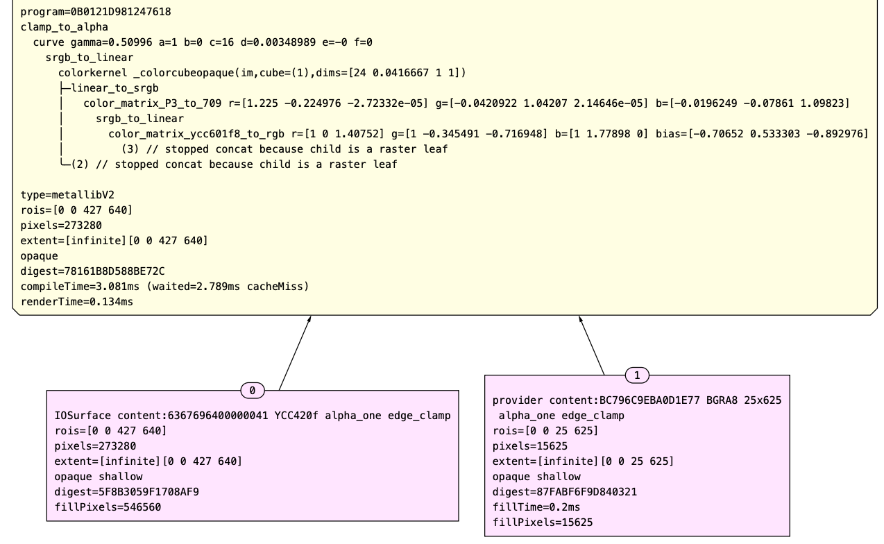
Key notes:
The line starting with
colorkernel _colorcubeopaquemarks where the actual processing ofCIFilter.colorCubeWithColorSpaceoccurs.
It takes two samples: the input image in the Display P3 color space and the cube data (which is interpreted as a 25x625 linear image). The working color space of a
CIContextdefaults to Linear sRGB, as mentioned earlier.
The input image is first converted to RGB, and then is color matched from its color space of Display P3 to Linear sRGB color space. After that, it’s matched again-from Linear sRGB to the sRGB specified in the
CIFilter.colorCubeWithColorSpaceinstance.
Once the
colorkernelprocesses the image, it’s matched back to the working color space of currentCIContext.
Let’s try a different scenario. If we set the colorSpace property of CIFilter.colorCubeWithColorSpace to nil, we get the following result graph:

In this case, the intermediate image—already matched to the working color space—will directly participate in the colorkernel operation alongside the cube image.
In summary, the debug tool of Core Image is useful to check the actual rendering pipeline, especially for those APIs that have unclear documentation.
Afterwords
Color management is handled for developers within many Apple frameworks. While building a simple application doesn’t require deep knowledge of color theory or color management, understanding these concepts equips you to solve subtle and confusing issues that might otherwise go unnoticed.
I hope this blog series helps you better understand color and how color management works across Apple Frameworks. Thanks for reading!
If my blogs are helping you, please consider buying me a coffee via Alipay, since I am not able to set up a paid subscription in Substack 👇. I really appreciate your support.